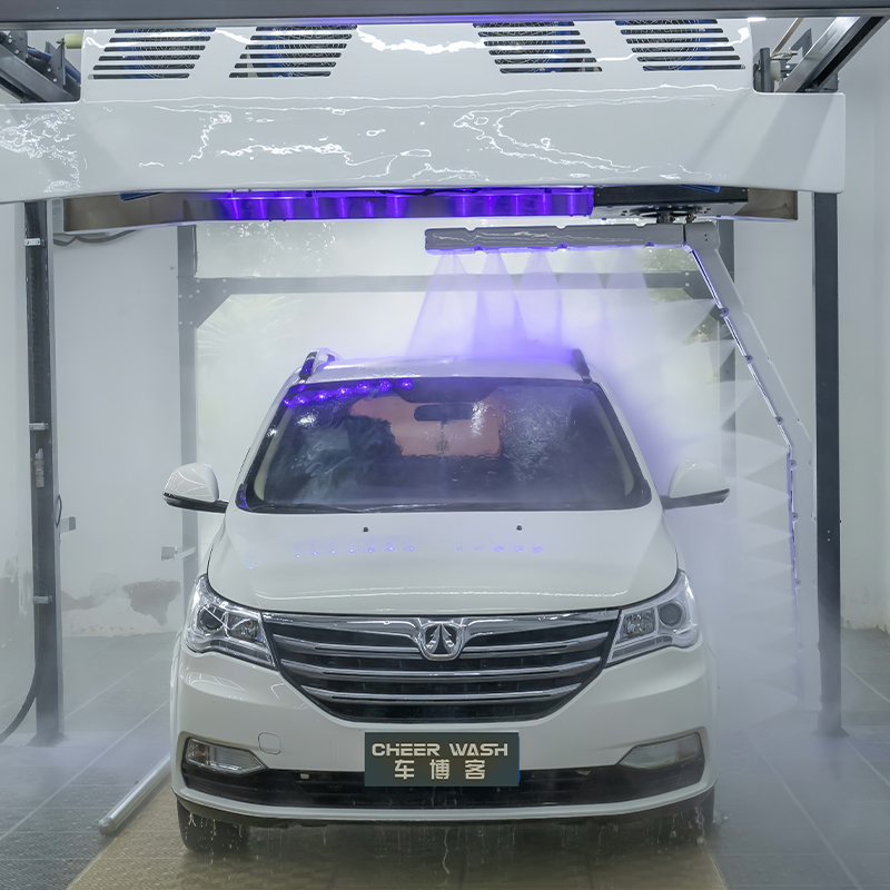
Installing a touchless wash system requires heavy capital. Site preparation dictates operational uptime, throughput, and return on investment. The physical environment acts as the foundation for daily operations. When site planning falls short, operators face severe consequences. Retrofitting utility lines, correcting improper concrete slopes post-pour, or miscalculating bay dimensions leads to cost overruns, premature equipment wear, and poor vehicle clearance. You must execute a precise technical blueprint for evaluating site readiness before the equipment arrives. Understanding the exact spatial, structural, and utility prerequisites is necessary to successfully deploy the CL800 Contactless Car Wash Machine. This guide breaks down the civil engineering, plumbing, and electrical thresholds required to transform an empty lot or outdated bay into a high-performing automated wash facility.
- Footprint & Clearances: A standard installation requires specific minimum bay dimensions (typically evaluating against a 2,000 to 4,000 sq. ft. total facility footprint) to accommodate the gantry, drying systems, and safe vehicle transit.
- Structural Integrity: Concrete foundations must meet strict PSI and thickness standards to safely anchor the heavy stainless steel fixed base and columns against high-torque operational vibrations.
- Utility Thresholds: Successful deployment demands verified access to robust 3-phase electrical power, high-GPM water supply, and adequate compressed air to drive high-pressure wash cycles.
- Compliance & Drainage: Integrated trench drains, oil/water interceptor pits, and water recycling compatibility are non-negotiable for environmental compliance and operational efficiency.
Spatial Prerequisites: Defining Your Contactless Wash Site Size
Undersized wash bays create immediate operational bottlenecks. When clearance is too tight, vehicle damage risks increase, maintenance access becomes restricted, and overall throughput drops. A properly sized bay ensures the gantry moves fluidly around the vehicle while leaving room for technicians to perform routine servicing without dismantling major components. You need space to pull wrenches, replace hoses, and inspect pumps.
Site layouts vary across different business models. Dedicated standalone wash bays offer flexibility, allowing developers to design the building footprint entirely around the equipment specifications. Gas station forecourts require tighter integration, sharing utility lines and traffic lanes with fuel pumps. Automotive dealership integrations demand rapid throughput to process inventory, necessitating optimized entry and exit flows. Retrofitting existing self-service wash bays presents unique challenges. The contactless wash site size must adapt to legacy brick-and-mortar constraints, whereas a new commercial build provides a blank canvas for optimal spatial planning.
Establishing minimum versus optimal bay dimensions prevents installation delays. The exact length, width, and height clearances required for the gantry must be strictly adhered to so the machine operates safely without contacting vehicles or structural walls. Beyond the physical footprint of the machine, operators must outline required buffer zones between the equipment frame and bay walls. These zones provide clearance for maintenance access, hose travel, and cable track movement during the dynamic wash cycle.
| Dimension Parameter | Minimum Requirement | Optimal Recommendation | Operational Impact |
| Bay Length | 28 Feet | 32+ Feet | Accommodates longer trucks and prevents overspray into exit lanes. |
| Bay Width | 14 Feet | 16 Feet | Allows safe gantry pass-around and technician maintenance access. |
| Ceiling Height | 11 Feet | 12+ Feet | Provides clearance for overhead cable tracks and standalone drying arches. |
| Equipment Room | 150 Sq. Ft. | 250 Sq. Ft. | Houses pump stations, RO systems, and electrical panels safely. |
Vehicle envelope clearance dictates what types of cars your facility can process. Defining maximum vehicle dimensions ensures compatibility with modern automotive designs. This includes accommodating wide-track SUVs, low-clearance electric vehicles, and trucks with aftermarket roof racks. Proper spatial planning addresses ultrasonic sensor placement and optical positioning array clearance. These sensors require unobstructed lines of sight to map the vehicle profile accurately, preventing blind spots or collisions during the automated wash cycle.
Beyond the wash bay, equipment room sizing requires attention. Auxiliary components need dedicated square footage in a climate-controlled environment. High-pressure pump stations, chemical dosing systems, water softener tanks, and electrical control panels must be housed securely with enough space for technicians to maneuver during repairs. Stacking equipment too tightly leads to overheating motors and impossible maintenance scenarios.
Traffic flow, entry terminals, and queuing lanes dictate the customer experience. Evaluating ingress and egress turning radii ensures smooth vehicle transitions into the bay, preventing tire damage on guide rails. Spatial and electrical conduit requirements must be mapped out early for integrating automatic payment terminals, RFID reader kiosks, and loop detectors at the entry point. Proper queuing lane length prevents traffic from spilling into public roadways during peak hours.
Structural & Civil Engineering Requirements for the CL800 Car Wash Machine
The structural requirements and civil preparation differ vastly between new builds and retrofitting older friction-wash bays. New builds allow for custom concrete pours tailored to the exact specifications of the equipment. Retrofits often require extensive concrete scanning, cutting, and re-pouring to correct legacy slopes or reinforce degraded foundations before installing the CL800 car wash machine.
Concrete foundation specifications form the backbone of a successful installation. The concrete compressive strength, measured in PSI, and the minimum slab thickness must support the static weight of the machinery and the dynamic, high-torque loads generated during operation. We recommend a minimum of 3,000 to 4,000 PSI concrete with a 6-inch thickness for the main bay floor. Furthermore, the floor slope grades must be engineered for optimal water runoff toward the drainage trench. This slope must aggressively channel water away from the bay floor without compromising the precise leveling required for the gantry tracks. A standard pitch of 1/4 inch per foot toward the center trench is standard practice.
Frame anchoring and column installation follow a precise mechanical sequence. Technicians must execute the following steps to ensure structural integrity:
- Measure and snap chalk lines for the bay centerlines to ensure perfect symmetry.
- Position the base plates and mark the exact locations for the anchor bolts.
- Drill anchor holes into the cured concrete using a rotary hammer, ensuring the correct depth and diameter.
- Clean the holes thoroughly with compressed air to remove concrete dust.
- Apply high-strength epoxy into the holes before inserting the wedge anchors to maximize pull-out resistance.
- Level the heavy stainless steel fixed base and columns using steel shims and precision laser levels.
- Torque all anchor nuts to the manufacturer's specified foot-pounds.
Vibration mitigation strategies prevent anchor fatigue. Utilizing heavy-duty vibration-damping pads under the base plates stops high-frequency vibrations from transferring directly into the concrete slab. This prevents micro-cracking and frame misalignment over the machine's lifecycle, ensuring the gantry runs smoothly along its tracks year after year.
Wall and ceiling materials must withstand a brutal operating environment. Continuous high-pressure water spray, aggressive cleaning chemicals, and fluctuating humidity levels will destroy standard building materials. Operators should utilize moisture-resistant, chemical-resistant, and high-impact materials for bay enclosures. Fiber-reinforced plastic (FRP) panels or extruded PVC wall systems are the industry standard. They provide a durable, easy-to-clean surface that prevents structural degradation and mold growth. Standard drywall or untreated plywood will fail within months.
![CL800 Contactless Car Wash Machine]()
Utility Thresholds: Power, Water, and Pneumatics
Utility specifications map directly to machine performance. Cycle speeds, which range from three to eight minutes, and final wash quality outcomes rely entirely on the facility's ability to deliver consistent power, water, and air pressure. Inadequate utilities throttle the machine's capabilities, leading to poor cleaning results and system faults. You cannot run a high-performance wash on undersized utility lines.
Electrical load and wiring demand careful planning. The equipment requires specific voltage, amperage, and robust 3-phase power to drive the high-pressure pumps and gantry motors simultaneously. Breaker sizing and dedicated circuit requirements must be strictly followed to prevent nuisance tripping. Given the wet environment, waterproof NEMA-rated enclosures and sealed conduits are mandatory. All electrical drops must be positioned exactly according to the manufacturer's CAD drawings to ensure safe and clean connections. Pulling the wrong gauge wire will result in voltage drops and burned-out contactors.
| Utility Type | Standard Requirement | Infrastructure Notes |
| Electrical Power | 208V - 480V, 3-Phase | Requires dedicated breaker panels and NEMA 4X waterproof enclosures in the wash bay. |
| Fresh Water Supply | 30 - 40 GPM Dynamic Flow | Minimum 1.5-inch to 2-inch supply line. Booster pumps required if municipal pressure is low. |
| Compressed Air | 10 - 15 CFM @ 90 PSI | Requires an industrial rotary screw or heavy-duty reciprocating compressor with an air dryer. |
| Water Softener | Sized to local water hardness | Prevents scale buildup in high-pressure pump valves and heater coils. |
Water supply and pressure standards dictate the cleaning power of a touchless system. The facility must deliver a specific dynamic flow rate, measured in Gallons Per Minute, alongside strict water pressure minimums. If the municipal supply cannot meet these demands, holding tanks and booster pumps become necessary. Integrating Reverse Osmosis (RO) systems for spot-free rinsing adds complexity. RO systems require specific plumbing routes, dedicated storage tanks, and secondary delivery pumps to ensure the final rinse leaves the vehicle completely free of mineral deposits. Hard water will clog nozzles and leave white spots on dark vehicles.
Compressed air specifications are often overlooked but remain vital for system operation. A reliable air compressor must deliver the exact Cubic Feet per Minute and pressure required to operate chemical foaming applicators, pneumatic directional valves, and arch positioning controls. Moisture traps and refrigerated air dryers should be installed in the pneumatic lines to prevent water intrusion from damaging sensitive solenoid valves. Water in the air lines will cause pneumatic cylinders to rust internally and fail prematurely.
Integrating the Car Wash Drying System
Drying performance is a major factor in customer satisfaction. Operators must evaluate the trade-offs between on-board gantry dryers and standalone freestanding drying arches. On-board systems save space but increase the cycle time, as the gantry must make an additional pass over the vehicle. Standalone arches allow the vehicle to dry as it exits the bay, increasing overall throughput, though they consume more footprint and require higher peak power.
The spatial and structural impact of a standalone car wash drying system is substantial. Additional bay length is required to prevent moisture carry-over from the wash zone into the exit lane. If the blower arch is placed too close to the final rinse arch, mist will compromise the drying process. Mounting heavy overhead blower motors requires robust supporting framework and structural reinforcement in the ceiling or side walls to handle the extreme torque generated during startup. A 15-horsepower blower motor creates significant rotational force when it kicks on.
Power draw and acoustic considerations are critical when integrating high-horsepower drying turbines. These motors require a massive electrical load, often necessitating a dedicated subpanel. High-decibel blower operations can trigger complaints from neighboring businesses or residential areas. Noise mitigation strategies, including acoustic paneling within the bay or utilizing variable frequency drives (VFDs) to soft-start the motors and control RPMs, are essential to comply with local municipal noise ordinances. VFDs also reduce the massive inrush current that occurs during motor startup, saving on peak demand utility charges.
Drainage, Water Recycling, and Environmental Compliance
Improper wastewater management carries severe legal, environmental, and operational risks. Failing to meet municipal discharge standards results in heavy fines, forced shutdowns, and grease trap failures. A well-engineered drainage system protects the business and the surrounding environment. You cannot simply dump wash water into a standard storm drain.
Trench drain sizing and placement must handle peak water volumes efficiently. The optimal location—whether a center trench running the length of the bay or a side trench—depends on the specific floor slope and equipment track layout. Grate load-bearing specifications must meet heavy vehicle traffic demands. Utilizing H-20 highway loading ratings ensures the grates will not collapse under the weight of heavy-duty pickup trucks or commercial vans. A collapsed grate will shut down your wash immediately and create a severe liability hazard.
Interceptor pits and oil/water separators are mandatory for capturing hazardous runoff. A multi-stage catch basin capacity is required to handle peak wash volumes, allowing time for heavy solids and sludge to settle at the bottom. These systems separate petroleum products, grease, and chemical surfactants before discharging the remaining wastewater to the municipal sewer system. Regular pumping and maintenance of these pits are required to prevent backups into the wash bay.
Water reclamation and recycling system integration is necessary in regions with strict environmental regulations or high utility costs. Plumbing and filtration prerequisites must be established early to route runoff into electric water recycling units. These systems filter and treat the water, allowing it to be reused for the high-pressure undercarriage or initial friction passes. This setup reduces utility costs, meets local eco-compliance standards, and minimizes fresh water consumption. You must plan for the additional footprint and electrical requirements of the recycling tanks and ozone generators.
Automatic Car Wash Installation: Timeline and Risk Mitigation
Executing a flawless automatic car wash installation requires strict project management and proactive risk mitigation. Rushing the process or skipping verification steps leads to operational delays. You need a structured approach to get the doors open on time.
A comprehensive pre-installation site audit checklist is the first line of defense. Project managers must verify all civil, structural, and utility work before the equipment arrives on-site. This includes measuring the bay dimensions a final time, testing concrete curing levels, and confirming that all electrical and plumbing stubs match the manufacturer's technical drawings precisely. If a plumbing stub is off by six inches, it can prevent the gantry from clearing the wall.
Common installation bottlenecks frequently derail timelines. Mismatched plumbing stubs, inadequate electrical drops, or uneven concrete slabs are frequent points of failure. Proactively mitigating these issues involves maintaining open communication between the general contractor, the electricians, and the equipment manufacturer. Catching a misplaced conduit before the concrete is poured saves thousands of dollars and weeks of delay.
Commissioning and calibration represent the final steps of the installation. Technicians must execute the following procedures before opening to the public:
- Verify all mechanical anchors are torqued to specification.
- Test all emergency stop buttons and safety break-away mechanisms.
- Calibrate ultrasonic sensors and optical arrays using test vehicles of varying sizes.
- Perform chemical dosing dilution testing to ensure the correct ratio of soap to water is applied.
- Conduct vehicle safety envelope dry-runs to confirm the gantry clears all mirrors and bumpers.
- Test the point-of-sale integration to ensure wash codes trigger the correct equipment cycles.
Conclusion
- Hire a licensed civil engineer to conduct a formal site survey and verify your existing concrete slab and utility capacities.
- Submit the manufacturer's technical CAD drawings to your local municipality to secure all necessary environmental, plumbing, and zoning permits.
- Contract a specialized commercial plumber and electrician with proven experience in high-voltage, wet-environment industrial installations.
- Order your water softener and reverse osmosis systems early to ensure they are plumbed and operational before the main wash equipment arrives.
FAQ
Q: What is the minimum contactless wash site size required for the CL800?
A: A standard installation requires a facility footprint of 2,000 to 4,000 square feet. The bay must provide adequate length, width, and height clearances for the gantry to move safely around maximum-sized vehicles, plus buffer zones for maintenance access and hose travel.
Q: How much electrical power does the CL800 car wash machine require?
A: The system requires robust 3-phase electrical power to operate high-pressure pumps and gantry motors simultaneously. Specific voltage and amperage requirements dictate dedicated circuit breakers and the use of waterproof NEMA-rated enclosures for all electrical connections.
Q: Can I retrofit an existing friction wash bay for a touchless system?
A: Yes. However, it often requires concrete scanning, cutting, and re-pouring to correct legacy floor slopes, upgrade drainage trenches, and ensure the foundation meets the strict PSI and thickness standards needed to anchor the new equipment safely.
Q: What are the specific drainage requirements for a touchless automatic car wash?
A: The bay must feature an aggressively sloped concrete floor directing water into a heavy-duty trench drain rated for H-20 highway loading. Runoff must flow into a multi-stage interceptor pit and oil/water separator before municipal sewer discharge.
Q: How long does the automatic car wash installation process typically take?
A: Once all civil, electrical, and plumbing site prep is fully completed and verified, the mechanical installation, wiring, chemical calibration, and safety commissioning typically take between one to two weeks, depending on the complexity of auxiliary systems.
Q: Does the car wash drying system require a separate dedicated power supply?
A: Yes. Standalone high-horsepower drying turbines draw a massive electrical load upon startup. They require a dedicated subpanel, specific breaker sizing, and variable frequency drives to manage the power spike and control acoustic output.